RCATheremin.com
Converting a Radiola 60 SPU to an RCA Theremin SPU
The Socket Power Unit (SPU) of an RCA Radiola 60 radio can be converted to be a functional equivalent of the SPU in the RCA Theremin, with a few simple rewiring changes and a capacitor. The following images and instructions make the conversion easy, and provide tips to convey an authentic appearance. Schematics for both SPUs are located at the bottom.
SPU Chassis Wiring
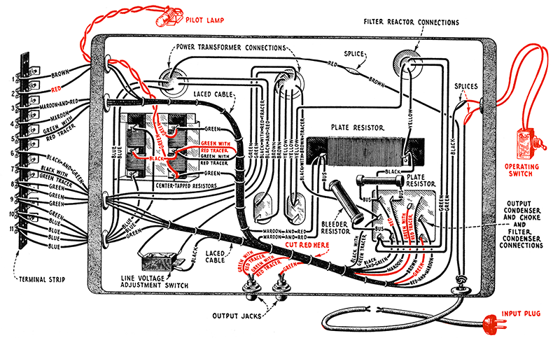
Radiola 60 chassis. Remove or modify the items colored in red. See instructions for details.
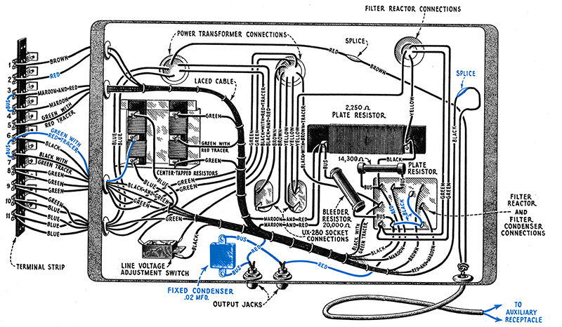
RCA Theremin chassis. Add or modify the items colored in blue. See instructions for details.
Instructions
- Eliminte the pilot lamp by removing its wires at the terminals of the wirewound resistor.
- Desolder the wires from the center tap terminals of the parallel, flat wirewound resistors, removing the black wire and lifting the two “green with red tracer” wires, and prepare the terminals receive fresh solder.
- With a multimeter, determine which “green with red tracer” wire connects to terminal number 5 on the terminal strip and solder it back to the center tapped terminal.
- Desolder the wires from both output jacks and prepare the terminals to receive fresh solder. The jacks can be unscrewed and removed from the chassis for easier preparation. To minimize the chance of fracturing the aged fiber washers, maintain their orientation when reinstalling. For both jacks, lightly spread the terminal leaves to form a V.
- Desolder the “green with red tracer” wire and the green wire at the filter condenser terminals. Prepare the terminals to receive fresh solder.
- Remove from the laced cable bundle the two “green with red tracer” wires and the green wire.
- Using one of the “green with red tracer” wires just removed, prepare and connect one end to the center tap of the left parallel, flat wirewound resistor. Feed the wire through the middle grommet on the chassis by putting a short length of heat shrink around the end to prevent the cloth covering from fraying. It is a tight fit but it can be done.
- Prepare about an inch of 20 gauge AWG wire (or salvaged bus wire from the Radiola 60) for connecting terminals 6 and 7 together.
- Desolder the "black and green" wire from terminal number 6 and remove the solder.
- Solder the "black and green", the “green with red tracer”, and the bus wire to terminal number 6 in the same way the other terminals are connected.
- Bend the bus wire around to terminal number 7, melt the existing solder, and insert the wire.
- Connect terminals 3 and 4 with bus wire in a similar manner of melting the existing solder and inserting the wire.
- Follow the red wire connected at terminal number 2 on the terminal strip and cut at the location shown. The right side of the wire should be about 3 inches long. Pull the left end out one or two turns from the laced cable bundle and the right side completely out of the laced cable bundle. Strip back about ¼ inch of insulation and prepare the ends for soldering.
- prepare the 0.02 MFD capacitor. For an authentic appearance, use a vintage Aerovox mica capacitor. Use 20 gauge AWG wire or salvaged bus wire from the Radiola 60. Clean surfaces and solder about 1½ inch of wire to both ends of the capacitor.
- Solder the red wires and the capacitor bus wires to the output jacks. Cut down the bus wires as needed. Make sure the capacitor and wires do not touch the filament pins of the UX-280 tube socket. For a more authentic RCA Theremin appearance, solder the Aerovox capacitors to the outside leaves of the output jacks and the red wires to the inside leaves.
- Add the black wires to the filter condenser terminals. Use solid core black wires salvaged from the Radiola 60. To connect the wire to the terminal with the bleeder resistor and “black and green” wire, desolder all wires, prepare the terminal to receive fresh solder, then add all three wires and solder.
- Unwrap the fabric tape of the splices for the operating switch and put aside. Cut the switch out at the splice points. Cut back the insulation and prepare the wires for joining the two ends inside the chassis. Slide a bit of heat shrink over one wire, solder the wires together, then heat shrink the connection. Take one of the splice fabric tape lengths, apply some glue and wrap over the heat shrink for a more vintage, original appearance.
- Leave 12 inches of the original power cord length and cut and prepare the ends for the auxiliary receptacle. Glue down or heat shrink the outer brown fabric to prevent fraying.
- For a more authentic appearance, remove the brass tag on the chassis by drilling out the two rivets from the underside, stepping up in drill bit sizes until the rivet can be pushed out, being careful not to drill into the chassis. On the other side, unscrew the machine screw holding the tag if it is the larger style tag. Remove the tag and then replace the screw and lock-washer.
- If you are replacing an original RCA Theremin SPU, keep the original with the theremin for its historical value.
SPU Schematics
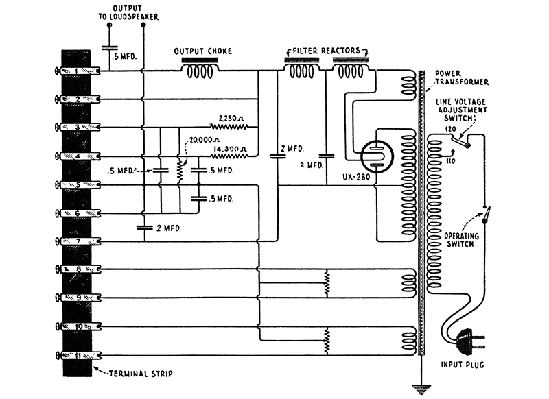
Radiola 60 SPU Schematic
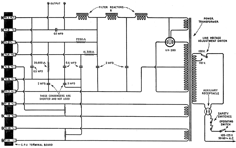
RCA Theremin SPU Schematic